

What Is Mechanical Joint Restraint for Ductile Iron Pipe and Why Is It Important?
Introduction
In water, wastewater, and industrial pipeline infrastructure, ductile iron pipe (DIP) remains a preferred material due to its strength, durability, and long service life. However, the overall performance and reliability of a ductile iron pipeline depend not only on the pipe itself, but also on how securely each joint is restrained.
This is where mechanical joint restraint for ductile iron pipe plays a critical role. While standard mechanical joints provide an effective watertight seal, they do not inherently prevent axial movement caused by internal pressure, changes in flow direction, or external loads. Without proper restraint, joints may separate, leading to leakage, pipe displacement, or costly system failures.
This guide explains what mechanical joint restraint is, how it works, why it is required, the most common restraint types used in ductile iron pipe systems, installation best practices, and how to select the appropriate solution for your project.
 showing dual glands and locking")
What Is Mechanical Joint Restraint for Ductile Iron Pipe?
A mechanical joint restraint is a device or system designed to prevent longitudinal movement and separation at a mechanical joint connection.
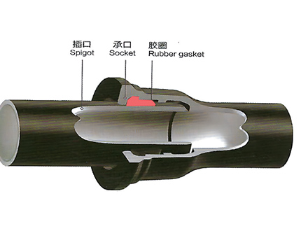
In ductile iron piping, a standard mechanical joint consists of:
A bell and spigot pipe or fitting
A rubber gasket to create a watertight seal
A follower gland and bolts to compress the gasket
While this configuration ensures sealing, it does not provide resistance against thrust forces. A mechanical joint restraint adds a dedicated restraining mechanism—such as wedges, serrated rings, or harness components—that grips the pipe or fitting and transfers axial forces safely through the pipeline system.
By restraining joint movement, these systems help maintain alignment, prevent leakage, and protect the structural integrity of the pipeline.
Why Is Mechanical Joint Restraint Required in Ductile Iron Pipe Systems?
1. Prevent Joint Separation and Leakage
Unrestrained mechanical joints may experience separation under internal pressure and thrust forces, depending on pipe diameter, system configuration, and operating conditions. Mechanical joint restraints provide controlled resistance to these forces, keeping joints intact and leak-free.
2. Reduce or Eliminate the Need for Thrust Blocks
Traditional thrust blocks rely on surrounding soil to resist thrust forces at bends, tees, valves, and dead ends. Mechanical joint restraints can significantly reduce or eliminate the need for concrete thrust blocks, especially where space is limited, soil conditions are poor, or faster installation is required.
3. Improve System Safety and Reliability
Restrained joints enhance pipeline stability, reducing the risk of sudden failures that could result in water loss, service disruption, or infrastructure damage. This is particularly important in high-pressure systems, seismic zones, or areas subject to ground movement.
4. Meet Engineering and Municipal Requirements
Many project specifications and municipal standards require restrained joints for ductile iron pipe systems to comply with AWWA, ANSI, or local design guidelines.
What Are the Common Types of Mechanical Joint Restraints for Ductile Iron Pipe?
Several restraint designs are widely used across the industry. The most common types include:
1. Split Serrated Gland Restraints
Description:
Split mechanical joint restraints that install over an existing mechanical joint without disassembling the connection.
Key Features:
Split design allows installation on existing pipelines
Serrated rings grip the pipe surface
Suitable for valves, fittings, hydrants, and appurtenances
Available in a wide range of pipe sizes
Applications:
Ideal for retrofitting existing mechanical joints and for projects requiring flexibility during installation.
2. Dual-Purpose Mechanical Joint Gland Restraints
Description:
Mechanical joint glands that combine gasket compression and joint restraint into a single assembly.
Key Features:
Designed for ductile iron pipe and compatible fittings
Serrated or wedge-based restraint components
Simplifies installation by reducing component count
Applications:
Commonly used in new pipeline installations where restrained mechanical joints are required.
3. Factory-Fabricated Restrained Mechanical Joints
Description:
Pre-manufactured restrained joint systems assembled at the factory.
Key Features:
Integrated sealing and restraint
Consistent factory-controlled quality
Rated for high working pressures
Applications:
Used in projects where retainer glands are restricted, or where long-term reliability and minimal field assembly are priorities.

4. Wedge-Type Mechanical Joint Restraints
Description:
Restraint systems using individually activated wedges that grip the pipe circumference.
Key Features:
Visual torque indicators for proper installation
High pressure ratings
Compatible with new installations and retrofits
Applications:
Widely applied in municipal water and wastewater systems.
5. Harness Systems and Split Gland Assemblies
Description:
Mechanical restraint systems that distribute thrust forces across multiple joints.
Key Features:
Suitable for large-diameter pipes
Various pressure ratings available
Flexible system configurations
Applications:
Used where thrust forces are high or where additional security is required across multiple pipe joints.
How Do Mechanical Joint Restraints Work to Protect Pipelines?
Mechanical joint restraints function by combining sealing and load resistance:
Wedge or Serrated Engagement
Restraint components grip the pipe surface when bolts are tightened.Load Transfer
Axial thrust forces are transferred from the pipe to the restraint mechanism and distributed along the pipeline.Bolted Compression
Bolts apply controlled force to activate the restraint while maintaining joint alignment.Sealing Function
A separate gasket compression mechanism maintains a watertight seal independent of the restraint.
This dual-function approach ensures both leak prevention and joint stability under operating and external loads.
How Should Mechanical Joint Restraints Be Installed Correctly?
Proper installation is essential for performance and long-term reliability.
1. Preparation
Follow all safety procedures and wear appropriate PPE
Clean the pipe spigot and bell socket thoroughly
Inspect gaskets, bolts, and restraint components
2. Joint Assembly
Position the restraint gland or ring on the pipe spigot
Lubricate the gasket as recommended
Insert the spigot fully into the bell
Seat the gasket correctly in the bell recess
Slide the restraint into position and insert bolts
3. Bolt Tightening
Hand-tighten bolts evenly
Use a torque wrench and tighten in a crisscross pattern
Follow manufacturer torque specifications, often requiring multiple passes
4. Inspection
Verify uniform bolt torque
Confirm proper restraint engagement
Check joint alignment before backfilling
What Are the Advantages of Using Mechanical Joint Restraints Compared to Thrust Blocks?
Enhanced pipeline durability and service life
Reduced need for concrete thrust blocks
Faster installation and reduced labor costs
Compatibility with various pipe sizes and pressure classes
Compliance with AWWA and ANSI standards
Improved resistance to seismic activity and soil movement
How Do You Select the Right Mechanical Joint Restraint for Your Project?
Factor | Considerations |
Pipe Size | Ensure compatibility with pipe diameter and class |
Pressure Rating | Match or exceed system operating pressure |
Application | New installation or retrofit |
Installation Constraints | Space, access, or need for split design |
Project Specifications | Municipal or consultant requirements |
Material Compatibility | Ductile iron pipe and fittings |
Cost & Availability | Budget and supply considerations |
Consulting with experienced manufacturers or pipeline specialists is recommended for final selection.
How Can Mechanical Joint Restraints Improve Pipeline Performance in Real Projects?
In a municipal water transmission project experiencing joint movement due to pressure fluctuations, a factory-fabricated restrained mechanical joint system was adopted.
Results included:
No reported joint separations over multiple years of operation
Reduced maintenance and inspection requirements
Faster field installation due to pre-assembled joints
Compliance with local specifications restricting retainer glands
Take Action
Are you planning a water supply or sewage project
For more technical insights and product options, visit:
 GT-type Joint Ductile Iron Pipe
 Sewage Pipe (Ductile Iron Sewage Pipe)
 Special Coating Pipe (Ductile Iron Pipe with Special Coatings)