

Comprehensive Guide to Ductile Iron Pipe Fittings: Types, Applications & Joint Compatibility

In ductile iron pipe systems, pipe material quality is important, but the scientific selection and proper installation of joints and fittings are equally critical. Fittings determine the reliability of pipe direction changes, branch connections, and diameter transitions, directly affecting the sealing, pressure resistance, and construction efficiency of the entire network. This article provides a systematic overview of the main ductile iron pipe fittings, their core functions, technical features, application scenarios, and compatibility with joints, helping with project selection and installation.
For more information, please refer to:
1. Definition and Core Functions of Fittings
Ductile iron pipe fittings are the "joints" of a pipeline system, used to achieve the following functions:
Change pipe direction (Elbows)
Divert or merge flow (Tees, Crosses)
Connect pipes of different diameters (Reducers)
Close pipe ends (End Caps / Blind Flanges)
The performance of fittings directly affects hydraulic performance, construction convenience, and long-term maintenance. Therefore, selection must consider pressure rating, pipe diameter, joint compatibility, and installation method.
2. Main Fitting Types and Technical Analysis
Type | Core Function | Typical Size | Key Technical Points | Application | Compatible Joints |
Elbow | Change pipe direction | 11.25°, 45°, 90° | Radius ~1.5D to reduce pressure loss | Directional pipelines, municipal networks | T-type, GT-type, Self-Anchored, Mechanical |
Tee / Cross | Flow diversion or merging | Equal DN100–DN600, Reducer DN100×80–DN600×400 | Branch connections must match main pipe diameter for sealing and flow balance | Branch pipelines, network distribution | T-type, GT-type, Self-Anchored, Mechanical |
Reducer | Connect different pipe diameters | Concentric / Eccentric | Eccentric used for horizontal installation to prevent sediment accumulation | Diameter transition, pump station inlets/outlets | T-type, GT-type, Self-Anchored, Mechanical |
End Cap / Blind Flange | Pipe end closure | DN50–DN300 | Socket with gasket or flange for easy removal | Pipe ends, temporary closures | T-type, GT-type, Self-Anchored, Flanged |
Technical Notes:
Fitting material should match the pipe or meet relevant standards to ensure pressure and corrosion resistance.
Elbows, Tees, and Reducers must have curvature radius proportional to pipe diameter to minimize turbulence and local pressure loss.
End Caps / Blind Flanges must guarantee sealing and allow for future removal or pipe extension.

3. Fitting Selection Guide
By Engineering Scenario
Municipal water and sewage networks: T-type / GT-type joints + standard elbows and Tees → flexible to ground settlement, fast construction.
Pump stations and equipment connections: Flanged joints + Reducers and Tees → easy equipment installation and maintenance.
Complex geological sections (steep slopes, settlement areas): Self-Anchored joints + elbows, Tees → strong axial restraint for critical nodes.
Trenchless construction (jacking / HDD): Jacking/HDD joints + elbows, reducers → withstand jacking and pulling forces, ensure pipe stability.
Key Parameter Control
Pressure rating: PN10 (1.0MPa) for normal municipal networks; PN16 (1.6MPa) for high-pressure or pump station outlets.
Diameter matching: Distinguish concentric/eccentric reducers; horizontal pipes should use eccentric reducers to avoid sediment accumulation.
Gasket material: Nitrile rubber (general), EPDM (high-temperature), Fluoroelastomer (chemical-resistant).
Joint Compatibility
Elbows, Tees, Reducers, and End Caps must be compatible with the selected joint type to ensure construction convenience, system sealing, and long-term durability.
4. Key Construction Requirements
On-site Inspection
Inspect pipes, gaskets, and fittings before installation. Replace any damaged, cracked, or deformed components.
Cleaning and Lubrication
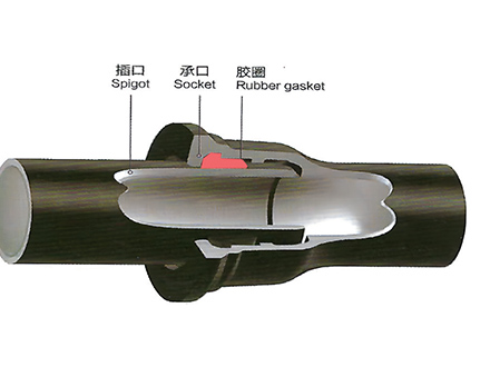
Thoroughly clean sockets, spigots, and gasket grooves. Apply recommended water-based lubricants to protect gaskets and reduce insertion resistance.
Accurate Positioning
Align the spigot center with the socket center and insert along the axis slowly to avoid twisting or displacing the gasket.
Anti-pull Measures
T-type or GT-type joints at horizontal/vertical elbows, Tees, or pipe ends require concrete thrust blocks or self-anchored locking mechanisms.
Special Joint Installation
Flanged joints: tighten bolts in a diagonal alternating pattern and in stages.
Mechanical and restrained joints: follow manufacturer installation sequence and torque precisely.
5. Common Mistakes and Preventive Measures
Mistake | Consequence | Preventive Measures |
Ignoring thrust blocks | Water pressure may push pipe sections out | Install concrete thrust blocks or use self-anchored joints at elbows, Tees, and critical nodes |
Over-rotating flexible joints | Gasket over-compression, leakage | Follow maximum allowable deflection angle for each joint type, use angled elbows to achieve turns |
Improper gasket installation | Gasket cutting, twisting, corrosion, leakage | Use water-based lubricants, ensure gasket is seated flat and fully inserted without twisting |
6. Conclusion
Ductile iron pipe fittings are essential for a reliable pipeline system. Scientific selection and correct installation ensure:
Smooth fluid flow and stable pressure
Reliable sealing and system safety
High construction efficiency and easy maintenance
Adaptability to various project conditions including municipal, industrial, high-pressure, and trenchless applications
It is recommended to combine this guide with the Ductile Iron Pipe Joint and Fitting Technical Guide to ensure elbows, Tees, reducers, and end caps are compatible with their corresponding joints, achieving an efficient, safe, and durable ductile iron pipe system.
 GT-type Joint Ductile Iron Pipe
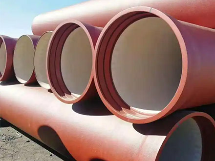
 Sewage Pipe (Ductile Iron Sewage Pipe)
 Special Coating Pipe (Ductile Iron Pipe with Special Coatings)