

Ductile Iron Pipe Installation and Testing: Trenching, Laying, Backfill, and Hydrostatic Test
The Part of the Job That Determines Everything
A well-specified pipe can still fail if installed poorly. I have walked sites where the pipe was the right DN, K class, and lining — but the trench was backfilled with rock, the joint was over-deflected, and the hydrostatic test was rushed. The result was the same as using the wrong material: leaks, delays, and disputes.
Ductile iron pipe installation is a sequence of controlled steps: trench geometry, bedding, joint assembly, alignment, backfill, compaction, and pressure testing. Each step creates constraints for the next one. If the bedding is uneven, the joint cannot seat correctly. If the joint is over-pulled, the gasket rolls. If the backfill is too rocky, the coating is damaged before the line is commissioned.
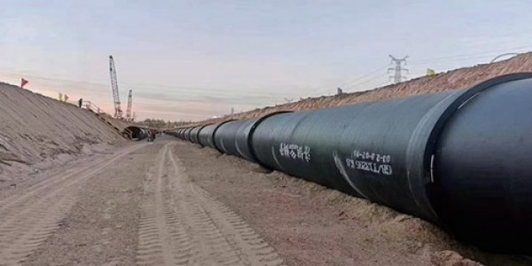
Trench Geometry: Width, Depth, and Slope
The trench must be wide enough for joint assembly and compaction, but not so wide that the pipe floats in uncompacted backfill. A common rule for ductile iron pipe installation is:
Trench width at pipe springline = pipe OD + 400–600 mm
Minimum cover for buried water mains in traffic areas = 1.0–1.2 m
Extra depth allowance for bedding = 100–150 mm below pipe invert
In soft or saturated clays — common in the Mekong Delta, Lagos, and coastal East Africa — the trench bottom must be over-excavated and replaced with stable granular bedding. I have seen contractors lay DN400 pipe directly on muddy trench bottoms after rainfall. The pipe settled differentially over the next wet season, creating tensile stress at joints and bell leaks.
Bedding and Pipe Support
Ductile iron pipe is stiff, but still needs uniform support along its length. The bedding should be:
Clean, granular material (sand or crushed stone, max 10–20 mm particle size)
Free of organic matter, clay lumps, and debris
Compacted to 90–95% of standard Proctor density in the haunch zone
The most common mistake is placing the pipe on a flat trench bottom without shaping the bedding into the pipe haunches. The pipe needs support across the bottom 120 degrees of its circumference. Without shaped bedding, the lower fibers carry more load than designed.
For rocky trenches — common in Zambia, Tanzania, and northern Vietnam — place a 100–150 mm sand bedding layer below and around the pipe before backfill. It is the difference between a 50-year service life and a first-dry-season leak repair.
Joint Assembly: Push-On and Flanged
Push-On Joints
Push-on joints are the default for buried ductile iron pipe installation. The sequence is:
Clean the bell and spigot.
Lubricate the spigot end and the gasket.
Insert the spigot into the bell until the reference mark reaches the correct insertion depth.
Check that the gasket is seated evenly.
Key control: mark the designed insertion depth on the spigot before assembly. A joint that is under-inserted will leak. A joint that is over-inserted may roll the gasket or reduce allowable angular deflection. For DN300, typical insertion depth is around 80–110 mm depending on the standard.
Angular deflection limits must be respected. A DN300 push-on joint may allow 3–5 degrees, but that is the maximum, not the design value. I recommend keeping field deflection below 50% of the allowable limit.
Flanged Joints
Flanged joints are used at valves, fittings, and above-ground connections. Tighten bolts in a star pattern and follow the standard torque table. Over-torquing can crack the flange ring.
Backfill: The Layer Everyone Rushes
Backfill is where most installation defects originate. It should be placed in lifts, compacted evenly on both sides of the pipe, and free of large stones or debris.
| Backfill Zone | Material | Compaction |
|---|---|---|
| Bedding | Sand or fine crushed stone | 90–95% Standard Proctor |
| Haunch | Same as bedding, hand-compacted under pipe | 90–95% Standard Proctor |
| Initial cover (0–300 mm over pipe) | Select backfill, max 20 mm particle | 90% Standard Proctor |
| Final backfill | Excavated material or imported fill | Per road or site spec |
A critical rule: do not dump backfill directly onto the pipe from height. I have seen excavator buckets drop rock-laden soil from 1.5 m onto DN200 pipe. The external coating was punctured at multiple points, creating future corrosion sites. Use a chute or place the first 300 mm by hand or lightweight equipment.
In high-water-table areas — coastal West Africa and river delta projects in Vietnam — backfill must be placed and compacted before the trench floods. Saturated backfill has no compaction value and creates voids that later collapse.
Hydrostatic Pressure Testing
Hydrostatic testing is the final verification, not a repair opportunity. The test should be performed after:
All joints are assembled and inspected
Initial backfill is in place (usually 300 mm minimum over pipe)
Fittings and appurtenances are properly anchored
The line is filled and air is vented
Standard test procedure: raise pressure to 1.5 times the working pressure or to the specification test pressure, hold for minimum 30 minutes, and measure leakage. For ductile iron pipe, allowable leakage is typically very low — often near zero for push-on joints if properly assembled.
Common test failures: trapped air, unanchored bends or tees moving under thrust, rolled gaskets, and flange bolts loosened by thermal expansion.
Field Cases Worth Remembering
The case studies below are composite scenarios drawn from typical project configurations and field experience.
Case 1: Urban water main in Ho Chi Minh City. A DN400 K9 push-on main was installed in a narrow corridor with mixed sand and clay backfill. The contractor compacted the trench with a plate compactor but did not place the first 300 mm by hand. A sharp stone punctured the coating at two locations. Corrosion started within 18 months, and both sections had to be replaced.
Case 2: Irrigation scheme in Tanzania. A 12 km DN300 pipeline crossed a seasonal river floodplain. The installer used native clay as backfill and did not replace the saturated trench bottom with granular bedding. After the first rainy season, differential settlement created a 2-degree joint deflection at several locations. Within three years, three joints showed minor leakage. Rebedding those sections with crushed stone stabilized the line. The lesson: floodplain trenches need engineered bedding, not just excavation refill.
Case 3: Industrial water loop in Lagos. A DN150 flanged branch connection was tested at 1.5 times working pressure without anchoring the tee. The tee rotated slightly, loosening the downstream flange bolts. The joint leaked at 12 bar, just below the test pressure. The failure was missing thrust restraint, not the flange or gasket. After installing concrete thrust blocks, the line passed testing and has operated without issue.
Practical Recommendations for Ductile Iron Pipe Installation
1. Write trench and backfill specifications as carefully as pipe specifications. A good pipe in a bad trench is a bad pipeline. Specify bedding material, compaction, and lift thickness in the contract.
2. Train the joint assembly crew before production laying starts. One untrained worker can roll a gasket in a DN500 joint that takes hours to find and repair.
3. Hold hydrostatic testing only after sufficient backfill is in place. Testing bare pipe creates unrealistic restraint conditions. Follow the standard: minimum cover before testing.
4. Inspect and document every joint. A simple log with chainage, joint number, and insertion depth makes future failures traceable.
5. Plan testing around water availability. In remote African or Southeast Asian sites, water may need to be trucked in. The test schedule should include filling time, soaking time, and test duration.
If you are preparing material specifications for a ductile iron pipe package and need help matching pipe size, pressure class, joint type, and lining/coating to your project conditions, send over the basic parameters. Tiegu Export's team can check the bill of materials against common Southeast Asian, African, and Middle Eastern water infrastructure configurations and provide a quotation and delivery schedule for the products involved. Email with project details for a product quotation.
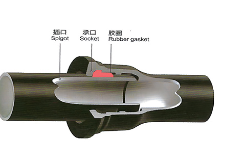 GT-type Joint Ductile Iron Pipe
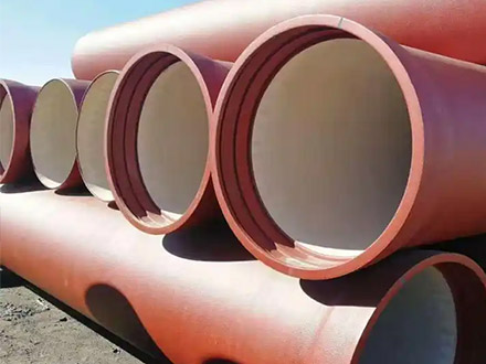
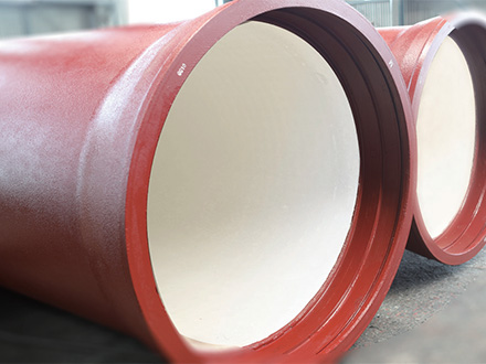 Sewage Pipe (Ductile Iron Sewage Pipe)
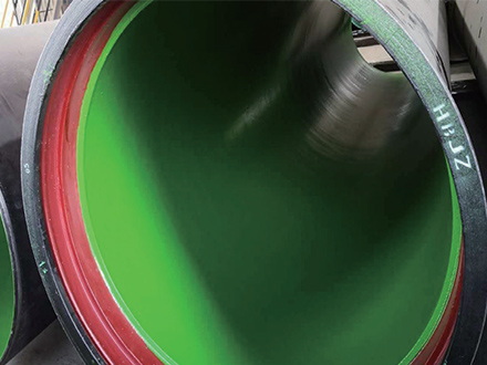 Special Coating Pipe (Ductile Iron Pipe with Special Coatings)