

What Are Standard Ductile Iron Pipe Sizes? DN80 to DN2000 Complete Guide

Table of Contents
What Are the Main Ductile Iron Pipe Sizing Standards?
How Does the DN (Diameter Nominal) System Work?
What Are the Complete Pipe Dimensions from DN80 to DN2000?
How Does Wall Thickness Vary by Pressure Class?
Which Pressure Class Should You Select for Your Project?
How to Calculate the Correct Pipe Size for Your Flow Requirements?
How to Specify Pipe Sizes for Your Water Infrastructure Project?
What Are the Main Ductile Iron Pipe Sizing Standards?
Ductile iron pipe dimensions follow two primary international standards that ensure compatibility across manufacturers and regions. Understanding these standards is essential for proper specification and procurement:
ISO 2531: International Standard
ISO 2531 "Ductile iron pipes, fittings, accessories and their joints for water or gas applications" is the most widely adopted standard globally. Key specifications:
Pressure Classes: K7, K8, K9, K10, K11, K12 (K9 is standard for water applications)
Size Range: DN40 to DN2600
Standard Length: 6 meters for DN40-DN600, 6-7 meters for DN700+
Outside Diameter: Fixed per DN size, constant across all pressure classes
Wall Thickness: Calculated per ISO formula: e = K × (0.5 + 0.001 × DN)
Cement Lining: Minimum 4mm for DN40-DN300, 6mm for DN350+
EN 545: European Standard
EN 545 "Ductile iron pipes, fittings, accessories and their joints for water pipelines - Requirements and test methods" is mandatory for European Union projects. Key differences:
Pressure Classes: PN10, PN16, PN25, PN35, PN40 (PN16 most common)
Testing Requirements: More stringent hydrostatic and mechanical testing protocols
Coating Standards: Specific requirements for zinc coating (130-200 g/m²) and cement lining
Certification: Requires third-party certification (KIWA, DVGW, NSF, WRAS)
Traceability: Full material traceability from casting to final inspection
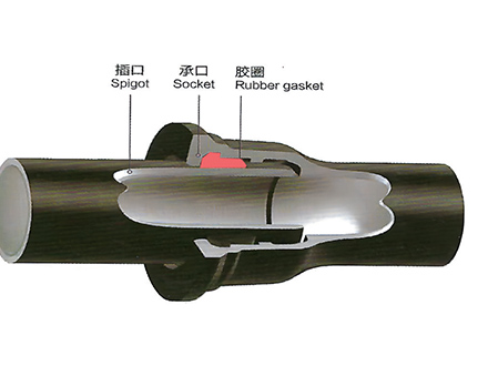
How Does the DN (Diameter Nominal) System Work?
The DN (Diameter Nominal) system designates pipe sizes by approximate internal diameter in millimeters. However, critical distinctions must be understood:
DN is NOT exact internal diameter — It's a nominal designation for compatibility and standardization
Outside diameter is constant for each DN size across all pressure classes and manufacturers
Internal diameter varies based on wall thickness (higher pressure class = thicker wall = smaller ID)
Example: DN300 Pipe Dimensions
| Pressure Class | Outside Diameter | Wall Thickness | Internal Diameter |
|---|---|---|---|
| K7 | 326 mm | 5.6 mm | 314.8 mm |
| K8 | 326 mm | 6.3 mm | 313.4 mm |
| K9 | 326 mm | 7.0 mm | 312.0 mm |
| K10 | 326 mm | 7.7 mm | 310.6 mm |
This standardization ensures that fittings and joints are interchangeable regardless of pressure class — a DN300 flange fits all DN300 pipes whether K9 or K10.
What Are the Complete Pipe Dimensions from DN80 to DN2000?
The following comprehensive table shows standard ductile iron pipe dimensions across the full size range commonly used in water infrastructure projects:
| DN (mm) | Outside Diameter (mm) | K7 (mm) | K8 (mm) | K9 (mm) | K10 (mm) | Length (m) | Application |
|---|---|---|---|---|---|---|---|
| DN80 | 98 | 3.0 | 3.5 | 4.0 | 4.5 | 6 | Building connections |
| DN100 | 118 | 3.5 | 4.0 | 4.5 | 5.0 | 6 | Residential distribution |
| DN150 | 170 | 4.0 | 4.5 | 5.0 | 5.6 | 6 | Street mains |
| DN200 | 222 | 4.5 | 5.0 | 5.6 | 6.3 | 6 | Commercial areas |
| DN250 | 274 | 5.0 | 5.6 | 6.3 | 7.0 | 6 | Industrial zones |
| DN300 | 326 | 5.6 | 6.3 | 7.0 | 7.7 | 6 | District mains |
| DN350 | 378 | 6.0 | 6.8 | 7.5 | 8.3 | 6 | Transmission lines |
| DN400 | 429 | 6.4 | 7.2 | 8.0 | 8.8 | 6 | City trunk lines |
| DN450 | 480 | 6.8 | 7.6 | 8.4 | 9.3 | 6 | Regional supply |
| DN500 | 532 | 7.2 | 8.0 | 8.8 | 9.7 | 6 | Major transmission |
| DN600 | 635 | 8.0 | 8.8 | 9.6 | 10.6 | 6 | Primary mains |
| DN700 | 738 | 8.8 | 9.6 | 10.4 | 11.5 | 6 | Intercity transfer |
| DN800 | 842 | 9.6 | 10.4 | 11.2 | 12.4 | 6 | Large transmission |
| DN900 | 945 | 10.4 | 11.2 | 12.0 | 13.2 | 6 | Regional transfer |
| DN1000 | 1048 | 11.2 | 12.0 | 12.8 | 14.0 | 6 | Mega projects |
| DN1200 | 1255 | 12.8 | 13.6 | 14.4 | 15.8 | 6 | Special applications |
| DN1400 | 1462 | 14.4 | 15.2 | 16.0 | 17.5 | 6 | Special applications |
| DN1600 | 1668 | 16.0 | 16.8 | 17.6 | 19.2 | 6 | Special applications |
| DN1800 | 1875 | 17.6 | 18.4 | 19.2 | 20.8 | 6 | Special applications |
| DN2000 | 2082 | 19.2 | 20.0 | 20.8 | 22.4 | 6 | Special applications |
How Does Wall Thickness Vary by Pressure Class?
ISO 2531 Wall Thickness Formula
Wall thickness for each pressure class is calculated using the ISO formula:
e = K × (0.5 + 0.001 × DN)
Where:
• e = minimum wall thickness (mm)
• K = pressure class coefficient (K7=7, K8=8, K9=9, K10=10)
• DN = nominal diameter (mm)
Example Calculation: DN500 K9 Pipe
e = 9 × (0.5 + 0.001 × 500)
e = 9 × (0.5 + 0.5)
e = 9 × 1.0 = 9.0mm (rounded to 8.8mm in practice)
Pressure Class Performance Comparison
| Pressure Class | Working Pressure | Surge Allowance | Design Pressure | Typical Applications |
|---|---|---|---|---|
| K7 | ≤6 bar | ≤8 bar | ≤8 bar | Low-pressure irrigation, gravity flow |
| K8 | ≤8 bar | ≤12 bar | ≤12 bar | Rural water supply, small networks |
| K9 | ≤10 bar | ≤16 bar | ≤16 bar | Municipal distribution (70% of projects) |
| K10 | ≤12 bar | ≤20 bar | ≤20 bar | High-pressure transmission, hilly terrain |
Which Pressure Class Should You Select for Your Project?
Pressure class selection depends on operating conditions, not just working pressure. Consider these factors:
Static Head (Elevation Changes)
For hilly terrain or tall buildings, calculate maximum static pressure at lowest point:
Static Pressure (bar) = Elevation Difference (m) ÷ 10
Example: 80m elevation difference = 8 bar static pressure
Add 2 bar residual pressure = 10 bar minimum working pressure → K9 required
Surge Pressure Analysis
Water hammer magnitude depends on:
Flow velocity: Higher velocity = larger surge (keep below 2 m/s for ductile iron)
Valve closure time: Rapid closure = higher surge (use slow-closing valves)
Pipeline length: Longer pipes = greater surge mass
Pump characteristics: Multiple pumps = complex surge patterns
General surge estimation:
Gravity systems: 2-4 bar surge allowance typically sufficient
Pumped systems: 6-10 bar surge allowance recommended
Long transmission mains: Detailed surge analysis required (use software like HAMMER, AFT Impulse)
External Load Considerations
For deep burial (>3m cover) or heavy traffic loads, thicker walls (K10 or higher) may be required for structural strength, even if pressure requirements are low.


How to Calculate the Correct Pipe Size for Your Flow Requirements?
Proper pipe sizing balances hydraulic efficiency, pressure loss, and lifecycle costs. Follow this systematic approach:
Step 1: Determine Design Flow Rate
Calculate peak demand considering:
Population served: Current + projected (20-30 year horizon)
Per capita consumption: 150-300 liters/day (varies by region)
Commercial/industrial demand: Separate calculation for large users
Fire flow requirements: Often governs sizing for distribution mains
Peak factor: 2.5-4.0x average daily demand for small systems
Step 2: Select Target Velocity
Optimal velocity range for ductile iron pipes:
Minimum: 0.6 m/s (prevents sedimentation, maintains water quality)
Economic: 1.0-1.5 m/s (balances pipe cost vs. pumping cost)
Maximum: 2.0 m/s (limits surge pressure, reduces friction losses)
Flow rate calculation:
Q = A × V
Where:
• Q = flow rate (m³/s)
• A = pipe cross-sectional area (m²) = π × (ID/2)²
• V = flow velocity (m/s)
Step 3: Calculate Friction Loss
Use Hazen-Williams equation for water pipes:
h_f = 10.67 × L × Q^1.852 ÷ (C^1.852 × D^4.87)
Where:
• h_f = friction head loss (m)
• L = pipe length (m)
• Q = flow rate (m³/s)
• C = roughness coefficient (140-150 for cement-lined DI pipe)
• D = internal diameter (m)
Acceptable friction loss: 1-3 m per km for transmission mains, 3-5 m/km for distribution networks.
Step 4: Verify Pressure Rating
Ensure selected pipe class withstands:
Maximum static pressure (elevation + reservoir level)
Surge pressure (pump startup/shutdown, valve closure)
Residual pressure (minimum 2 bar at highest point for consumer service)
How to Specify Pipe Sizes for Your Water Infrastructure Project?
If you are designing water transmission or distribution systems, selecting appropriate pipe sizes and pressure classes is critical for hydraulic performance and long-term reliability.
Tiegu integrates production capacity across qualified Chinese foundries, delivering compliant and high-quality casting products to buyers worldwide. For water infrastructure projects, we coordinate ductile iron pipe manufacturing with appropriate sizes (DN80-DN2000), pressure classes (K7-K12), and certifications (ISO 2531, EN 545) based on hydraulic calculations and project specifications.
Share your pipeline layout, flow requirements, and pressure conditions to receive supplier recommendations with appropriate pipe dimensions and competitive quotations.
📋 Get Free Technical Quotation
Summary Answer
Standard size range: DN80 to DN2000 per ISO 2531 and EN 545, with outside diameter constant per DN size
Pressure classes: K7-K12 (ISO) or PN10-PN40 (EN), with K9/PN16 most common for municipal water (10 bar working pressure)
Wall thickness: Calculated per ISO formula e = K × (0.5 + 0.001 × DN), varies by pressure class
DN80-DN600: Accounts for 70% of municipal water distribution projects
Standard length: 6 meters for all sizes (DN40-DN2000)
Size selection: Based on flow rate, target velocity (1.0-1.5 m/s), and friction loss (1-5 m/km)
📞 Contact Tiegu for Pipeline Solutions
WhatsApp / WeChat: +86 152 5613 5588
Email: zbw@tiegu.net
Website: www.ductileironpipe2600.com
Inquiry Form: Submit Your Requirements
Response Time: Within 24 hours
 GT-type Joint Ductile Iron Pipe
 Sewage Pipe (Ductile Iron Sewage Pipe)
 Special Coating Pipe (Ductile Iron Pipe with Special Coatings)