

How to Calculate Ductile Iron Pipe Wall Thickness? K7 K8 K9 K10 Complete Guide
How to Calculate Ductile Iron Pipe Wall Thickness? K7 K8 K9 K10 Complete Guide

, K10 for high-pressure transmission (12 bar)")
Table of Contents
What Is the ISO 2531 Pressure Class System?
ISO 2531 defines pressure classes using the "K" system, where K values represent pressure ratings with built-in surge allowance. Understanding this system is fundamental to proper pipe specification:
| Pressure Class | Working Pressure (PFA) | Surge Allowance | Design Pressure (PFA + Surge) | Typical Applications |
|---|---|---|---|---|
| K7 | 6 bar | 2 bar | 8 bar | Low-pressure irrigation, gravity flow systems |
| K8 | 8 bar | 4 bar | 12 bar | Rural water supply, small distribution networks |
| K9 | 10 bar | 6 bar | 16 bar | Municipal distribution (70% of projects) — STANDARD |
| K10 | 12 bar | 8 bar | 20 bar | High-pressure transmission, hilly terrain, pump discharge |
| K11 | 14 bar | 10 bar | 24 bar | Special high-pressure applications |
| K12 | 16 bar | 12 bar | 28 bar | Industrial applications, extreme conditions |
EN 545 PN Class Equivalent
European projects use EN 545 PN (Pressure Nominal) system instead of K classes:
ISO 2531 K9 ≈ EN 545 PN16 (both allow 10 bar working pressure)
ISO 2531 K10 ≈ EN 545 PN25 (both allow 12 bar working pressure)
ISO 2531 K12 ≈ EN 545 PN40 (both allow 16 bar working pressure)
For international tenders, specify "ISO 2531 K9 or equivalent EN 545 PN16" to allow supplier flexibility while maintaining performance requirements.
How to Calculate Wall Thickness Using ISO Formula?
ISO 2531 specifies a linear formula for minimum wall thickness based on pressure class and nominal diameter:
e = K × (0.5 + 0.001 × DN)
Where:
• e = minimum wall thickness (mm)
• K = pressure class coefficient (7, 8, 9, 10, 11, 12)
• DN = nominal diameter (mm)
Step-by-Step Calculation Examples
Example 1: DN300 K9 Pipe
e = 9 × (0.5 + 0.001 × 300)
e = 9 × (0.5 + 0.3)
e = 9 × 0.8
e = 7.2mm → rounded to 7.0mm (standard thickness)
Example 2: DN500 K9 Pipe
e = 9 × (0.5 + 0.001 × 500)
e = 9 × (0.5 + 0.5)
e = 9 × 1.0
e = 9.0mm → rounded to 8.8mm (standard thickness)
Example 3: DN500 K10 Pipe (High Pressure)
e = 10 × (0.5 + 0.001 × 500)
e = 10 × (0.5 + 0.5)
e = 10 × 1.0
e = 10.0mm → rounded to 9.7mm (standard thickness)
What Are the Standard Wall Thicknesses for DN80-DN2000?
Complete wall thickness reference table for all standard sizes and pressure classes:
| DN | OD (mm) | K7 (mm) | K8 (mm) | K9 (mm) | K10 (mm) | K9 Weight (kg/m) | K9 Water Content (L/m) |
|---|---|---|---|---|---|---|---|
| DN80 | 98 | 3.0 | 3.5 | 4.0 | 4.5 | 14.8 | 5.7 |
| DN100 | 118 | 3.5 | 4.0 | 4.5 | 5.0 | 21.2 | 8.5 |
| DN150 | 170 | 4.0 | 4.5 | 5.0 | 5.6 | 32.5 | 18.1 |
| DN200 | 222 | 4.5 | 5.0 | 5.6 | 6.3 | 45.8 | 30.2 |
| DN250 | 274 | 5.0 | 5.6 | 6.3 | 7.0 | 62.4 | 46.6 |
| DN300 | 326 | 5.6 | 6.3 | 7.0 | 7.7 | 82.1 | 67.9 |
| DN350 | 378 | 6.0 | 6.8 | 7.5 | 8.3 | 104 | 95.0 |
| DN400 | 429 | 6.4 | 7.2 | 8.0 | 8.8 | 129 | 125 |
| DN450 | 480 | 6.8 | 7.6 | 8.4 | 9.3 | 155 | 159 |
| DN500 | 532 | 7.2 | 8.0 | 8.8 | 9.7 | 184 | 196 |
| DN600 | 635 | 8.0 | 8.8 | 9.6 | 10.6 | 245 | 284 |
| DN700 | 738 | 8.8 | 9.6 | 10.4 | 11.5 | 312 | 391 |
| DN800 | 842 | 9.6 | 10.4 | 11.2 | 12.4 | 385 | 515 |
| DN900 | 945 | 10.4 | 11.2 | 12.0 | 13.2 | 465 | 657 |
| DN1000 | 1048 | 11.2 | 12.0 | 12.8 | 14.0 | 552 | 815 |
| DN1200 | 1255 | 12.8 | 13.6 | 14.4 | 15.8 | 745 | 1,170 |
| DN1400 | 1462 | 14.4 | 15.2 | 16.0 | 17.5 | 965 | 1,585 |
| DN1600 | 1668 | 16.0 | 16.8 | 17.6 | 19.2 | 1,215 | 2,050 |
| DN1800 | 1875 | 17.6 | 18.4 | 19.2 | 20.8 | 1,495 | 2,590 |
| DN2000 | 2082 | 19.2 | 20.0 | 20.8 | 22.4 | 1,805 | 3,205 |
What Is the Difference Between Working Pressure and Design Pressure?
Confusing these terms leads to dangerous undersizing or wasteful oversizing:
Working Pressure (PFA - Pressure Allowable for Fluid)
Definition: Maximum continuous operating pressure the pipe can withstand during normal service.
Includes:
Static pressure (elevation head + reservoir level)
Normal pump operating pressure
Friction loss at design flow
Residual pressure at endpoints (minimum 2 bar)
Does NOT include: Surge pressure from water hammer
Design Pressure (PFA + Surge)
Definition: Maximum instantaneous pressure including surge allowance. This is what the pipe must withstand without failure.
Design Pressure = Working Pressure + Surge Allowance
Example: K9 pipe has 10 bar working pressure + 6 bar surge allowance = 16 bar design pressure
How to Calculate Surge Pressure (Water Hammer)?
Surge pressure occurs when flowing water is suddenly stopped or accelerated. The pressure wave travels at sonic velocity through the pipe, potentially causing catastrophic failure if not properly accounted for.
Joukowsky Equation (Instantaneous Valve Closure)
ΔP = ρ × a × ΔV
Where:
• ΔP = surge pressure (Pa)
• ρ = water density (1000 kg/m³)
• a = wave velocity (m/s) — typically 1000-1200 m/s for ductile iron
• ΔV = velocity change (m/s)
Simplified formula for ductile iron pipes:
ΔP (bar) ≈ 0.06 × V (m/s) × L (m) ÷ t (s)
Where:
• V = flow velocity (m/s)
• L = pipeline length (m)
• t = valve closure time (s)
Surge Pressure Guidelines
| System Type | Typical Surge (bar) | Recommended Class |
|---|---|---|
| Gravity flow (no pumps) | 2-4 bar | K8 or K9 |
| Pumped distribution (short mains) | 4-6 bar | K9 (standard) |
| Pumped transmission (long mains) | 6-10 bar | K10 or K11 |
| Pump discharge (near station) | 10-15 bar | K11 or K12 |

How Do External Loads Affect Wall Thickness Selection?
Internal pressure isn't the only consideration. External loads from soil weight, traffic, and installation handling may require thicker walls even when pressure requirements are low:
External Load Sources
Soil load: Weight of backfill above pipe (increases with burial depth)
Traffic load: Trucks, buses, heavy equipment passing above (AASHTO H-20 or HS-20 loading)
Construction loads: Temporary stockpiles, crane outriggers, excavation equipment
Handling loads: Lifting, transportation, installation stresses
Minimum Wall Thickness for External Loads
| Burial Depth | Traffic Loading | Minimum Pressure Class | Notes |
|---|---|---|---|
| < 1.5m | No traffic (greenfield) | K8 | Minimum for handling strength |
| 1.5-3.0m | Light traffic (cars only) | K9 | Standard for most applications |
| > 3.0m | Heavy traffic (trucks) | K10 or K11 | Required for deep burial under roads |
| Any depth | Airport runways, ports | K12 or special design | Extreme loading conditions |
Bedding Class Impact
Proper bedding reduces external load on pipe wall:
Class A (concrete cradle): Maximum support — allows thinner walls or deeper burial
Class B (compacted granular bedding): Standard support — use K9 for most applications
Class C (flat trench, minimal bedding): Poor support — requires thicker walls (K10+)
How to Specify Pressure Class for Your Pipeline Project?
If you are designing water transmission or distribution systems, proper pressure class selection requires careful analysis of operating conditions, surge potential, and external loads.
Tiegu integrates production capacity across qualified Chinese foundries, delivering compliant and high-quality casting products to buyers worldwide. For water infrastructure projects, we coordinate ductile iron pipe manufacturing with appropriate pressure classes (K7-K12), wall thicknesses, and certifications (ISO 2531, EN 545) based on hydraulic calculations and project specifications.
Share your pipeline profile, pump curves, and burial conditions to receive supplier recommendations with appropriate pressure classes and competitive quotations.
📋 Get Free Technical Quotation
Summary Answer
ISO 2531 formula: e = K × (0.5 + 0.001 × DN) — calculate minimum wall thickness for any pressure class
K9 is standard: 10 bar working pressure + 6 bar surge allowance suits 70% of municipal applications
Working vs design pressure: Design pressure = working pressure + surge allowance — always design for surge
Surge calculation: Use Joukowsky equation (ΔP = ρ × a × ΔV) or simplified formula (0.06 × V × L ÷ t)
External loads matter: Deep burial (>3m) or heavy traffic may require K10+ regardless of pressure requirements
Complete thickness table: DN80 (4.0mm K9) to DN2000 (20.8mm K9) — verify with supplier data sheets
📞 Contact Tiegu for Pipeline Solutions
WhatsApp / WeChat: +86 152 5613 5588
Email: zbw@tiegu.net
Website: www.ductileironpipe2600.com
Inquiry Form: Submit Your Requirements
Response Time: Within 24 hours
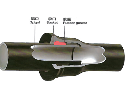 GT-type Joint Ductile Iron Pipe
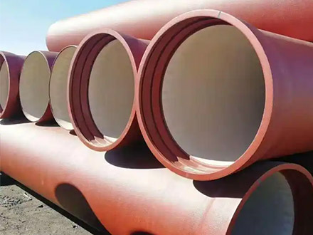
 Sewage Pipe (Ductile Iron Sewage Pipe)
 Special Coating Pipe (Ductile Iron Pipe with Special Coatings)