

Hydrostatic Testing Procedures for Ductile Iron Pipeline
Hydrostatic Testing Procedures for Ductile Iron Pipeline
Hydrostatic pressure testing is the final verification that a ductile iron pipeline is leak-free and structurally sound before commissioning. The test validates pipe integrity, joint assembly quality, thrust restraint effectiveness, and fitting connections. Proper test procedures, safety protocols, and acceptance criteria are essential to ensure reliable results and prevent damage to the pipeline. This comprehensive guide covers test planning, pressure calculations, filling procedures, leak detection, and acceptance criteria per ISO 10803 and industry standards.
Test Planning
Test Section Length
| DN Range | Maximum Test Length | Notes |
|---|---|---|
| DN80-300 | 500-1000m | Longer sections possible with adequate equipment |
| DN350-600 | 300-500m | Limited by water volume and pump capacity |
| DN700-1000 | 200-300m | Large water volume requires extended fill time |
| DN1100+ | 100-200m | Engineered test plan required |
Test Pressure Calculation
P_test = 1.5 × P_working (minimum 10 bar)
P_test = Hydrostatic test pressure (bar)
P_working = Maximum working pressure (bar)
Examples:
Working pressure 10 bar → Test pressure 15 bar
Working pressure 16 bar → Test pressure 24 bar
Working pressure 25 bar → Test pressure 37.5 bar
Water Volume Calculation
V = π × (D/2)² × L × 1000
V = Water volume (liters)
D = Inside diameter (m)
L = Test section length (m)
Example: DN400, 500m length
D = 0.429m (OD) - 2 × 0.008m (wall) = 0.413m (ID)
V = π × (0.413/2)² × 500 × 1000 = 67,100 liters
Fill time @ 100 L/min = 671 minutes = 11.2 hours
Pre-Test Preparation
Safety Checklist
☐ Thrust restraint verified (all fittings, valves, dead ends)
☐ Backfill completed (pipe covered, fittings exposed for inspection)
☐ Air valves installed (high points for air release)
☐ Drain valves installed (low points for drainage)
☐ Test pump calibrated (pressure gauge certification valid)
☐ Safety zone established (no personnel near pressurized line)
☐ Emergency procedures reviewed (depressurization method)
☐ Communication system (radio contact between test ends)
Equipment Requirements
| Equipment | Specification | Notes |
|---|---|---|
| Test pump | Capacity: 50-200 L/min, Pressure: 50+ bar | Positive displacement pump |
| Pressure gauge | Range: 0-40 bar (or higher), Accuracy: ±0.5% | Calibrated within 12 months |
| Recording device | Data logger or chart recorder | Continuous pressure monitoring |
| Air release valve | Automatic, DN25-DN50 | Install at all high points |
| Test headers | Steel plate with flanged connections | Seal test section ends |
| Hoses | High-pressure rated (1.5 × test pressure) | Connect pump to pipeline |
Test Procedure
Step 1: Fill Pipeline
Open air valves at all high points
Fill slowly (50-100 L/min for DN80-300)
Monitor air valves - close when water discharges
Continue filling until all air is expelled
Close all valves when pipeline is full
Step 2: Initial Pressurization
Connect test pump to pipeline
Pressurize to 1-2 bar (preliminary check)
Hold for 15 minutes
Inspect all joints, fittings, and valves for leaks
Repair any leaks before continuing
Step 3: Raise to Test Pressure
Increase pressure in 5 bar increments
Hold 5 minutes at each increment
Monitor for pressure drops or leaks
Continue until test pressure is reached
Record start time and initial pressure
Step 4: Test Duration
Maintain test pressure for minimum 2 hours
Record pressure every 15 minutes
Monitor for pressure drops
Inspect exposed joints and fittings
Document any leaks or issues
Step 5: Acceptance Criteria
Pressure drop ≤ 0.2 bar during test period
No visible leaks at joints or fittings
No joint movement or separation
No fitting displacement
If criteria not met, locate and repair leaks, then retest
Step 6: Depressurization
Open drain valve slowly
Allow controlled depressurization
Open air valves to prevent vacuum
Drain pipeline completely (if required)
Remove test equipment
Leak Detection Methods
Visual Inspection
| Method | Application | Limitations |
|---|---|---|
| Exposed joints | All accessible joints | Only detects visible leaks |
| Wet spots | Above-ground sections | Requires dry conditions |
| Sound detection | Quiet environments | Background noise interference |
Pressure Decay Analysis
ΔP_max = 0.2 bar (typical)
ΔP = Pressure drop during test (bar)
Accounts for minor temperature effects
Excessive drop indicates leak
Flow Measurement (for large leaks)
| Flow Rate | Leak Severity | Action |
|---|---|---|
| <0.5 L/min | Minor (acceptable) | Monitor, may seal naturally |
| 0.5-2 L/min | Moderate | Locate and repair |
| >2 L/min | Major | Immediate repair required |
Temperature Effects
Pressure-Temperature Relationship
ΔP = P × β × ΔT
β = Thermal expansion coefficient of water (0.00021/°C)
ΔT = Temperature change (°C)
Example: 15 bar test, temperature drops 5°C
ΔP = 15 × 0.00021 × 5 = 0.016 bar
Pressure drop from temperature is minimal
Large pressure drops indicate leaks, not temperature
Best Practices
Test during stable weather conditions
Avoid testing during large temperature swings
Record ambient temperature during test
Allow water temperature to stabilize before testing
Safety Precautions
High-Pressure Hazards
Hydrostatic testing involves stored energy. A DN400 pipeline at 24 bar contains enough energy to cause serious injury or death if failure occurs.
Safety Rules:
❌ Never stand near pressurized pipeline
❌ Never approach leaking joint under pressure
❌ Never exceed maximum test pressure
❌ Never use air for pressure testing (explosive hazard)
✅ Always establish safety exclusion zone
✅ Always use calibrated equipment
✅ Always have emergency depressurization plan
Supply Chain Perspective
Test Equipment and Third-Party Inspection
Hydrostatic testing requires calibrated pumps, pressure gauges, and recording devices. Some projects require third-party inspection to verify test procedures and witness results. Equipment availability varies by region. Tiegu integrates production capacity across qualified Chinese foundries, delivering compliant and high-quality casting products to buyers worldwide while coordinating with local testing services to ensure equipment availability and certified inspection when required by project specifications.
This prevents test delays from equipment shortages and ensures acceptance by project owners.
Submit your project location and testing requirements to confirm equipment availability and inspection services.
Test Documentation Checklist
☐ Test plan approved (section length, test pressure, duration)
☐ Equipment calibrated (pump, gauges, recording device)
☐ Safety briefing conducted (all personnel)
☐ Thrust restraint verified (pre-test inspection)
☐ Pressure recorded (every 15 minutes during test)
☐ Temperature recorded (ambient and water)
☐ Leaks documented (location, severity, repair method)
☐ Test certificate issued (signed by inspector/owner)
Conclusion
Hydrostatic testing verifies pipeline integrity before commissioning. Proper planning, safety protocols, and acceptance criteria ensure reliable results. Test pressure is 1.5 × working pressure for minimum 2 hours with maximum 0.2 bar pressure drop.
Key points:
Test pressure: 1.5 × working pressure (min 10 bar)
Duration: Minimum 2 hours
Acceptance: ≤0.2 bar drop, no visible leaks
Safety: Establish exclusion zone, never exceed max pressure
Documentation: Record pressure, temperature, and any leaks
For large-diameter or high-pressure pipelines, consider third-party inspection to verify test procedures and provide certification for project acceptance.
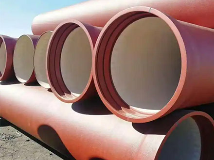
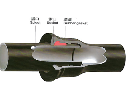 GT-type Joint Ductile Iron Pipe
 Sewage Pipe (Ductile Iron Sewage Pipe)
 Special Coating Pipe (Ductile Iron Pipe with Special Coatings)